Putsch
Putsch ist ein interaktives Theaterstück vom Planetenparty Prinzip in Koproduktion mit dem Landestheater Linz und LaStrada Graz.
Inhaltsverzeichnis
- 1 LoRa Netzwerk
- 2 Innere Stimme
- 3 Ortung der mobilen Clients im Spiel
- 4 Spiellogik
LoRa Netzwerk[Bearbeiten]
Wir verwenden Module im Frequenzbereich 433 MHz. Das ist die niedrigste Frequenz mit der größten Reichweite.
RSSID Signal bis zu -100db. (bis zu -80db ist eigentlich eine gute Signalstärke)
Hardware[Bearbeiten]
Microcontroller[Bearbeiten]
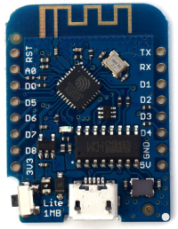
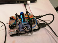
The WEMOS D1 mini Lite[1] boards were chosen to realise the LoRa hardware. They feature a ESP8285[2] from Espressif
Pitfalls
Special care has to be taken with Pin D3 on the WEMOS D1 mini Lite, as if this pin is held-low while startup, the ESP8285 goes into boot-mode. This causes chaos.
References
[1] WEMOS D1 mini lite homepage: https://www.wemos.cc/en/latest/d1/d1_mini_lite.html
[2] Espressif ESP8285 datasheet: https://www.espressif.com/sites/default/files/documentation/0a-esp8285_datasheet_en.pdf
LoRa Transciever-Modules[Bearbeiten]
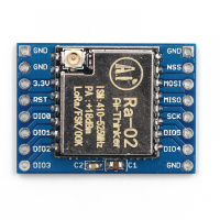
For receiving and sending LoRa-data, Ra-02 LoRa modules[3] from Ai-thinker are used. They use a Semtec[1] SX1278 chip[2].
Ra-02
The DIO0 pins on the Ra-02 can be ignored for our application. [2] Says that those pins are custom pins that can be software-configured. Antennas for those modules are set seperately because the carrier-frequency can be set via SPI on the SX1278.
Semtec SX1278
According to the datasheet they have 100 mW constant RF output and a programmable bit rate up to 300 kbps. Some parameters including the bitrate can be programmed via SPI. Range and stability are always a tradeoff, that is further described in [2, page 25]. The parameters Spreading Factor, Coding Rate and Signal Bandwidth can therefore be set.
"spreading factor and error correction rate are design variables that allow the designer to optimise the trade-off between occupied bandwidth, data rate, link budget improvement and immunity to interference" - [2, page 25]
Pitfalls
If the maximum Bandwidth (500kKz) on the SX1278 is selected, other paramters have to be adapted. (I try to find that statement in the datasheet again)
COMMENT - This needs to be looked up!
References
[1] Semtec website: https://www.semtech.com/products/wireless-rf/lora-connect/sx1278
[2] Semtec SX1278 dataheet: https://cdn-shop.adafruit.com/product-files/3179/sx1276_77_78_79.pdf
[3] Ai-thinker Ra-02 LoRa modules: https://docs.ai-thinker.com/_media/lora/docs/c048ps01a1_ra-02_product_specification_v1.1.pdf
Displays[Bearbeiten]
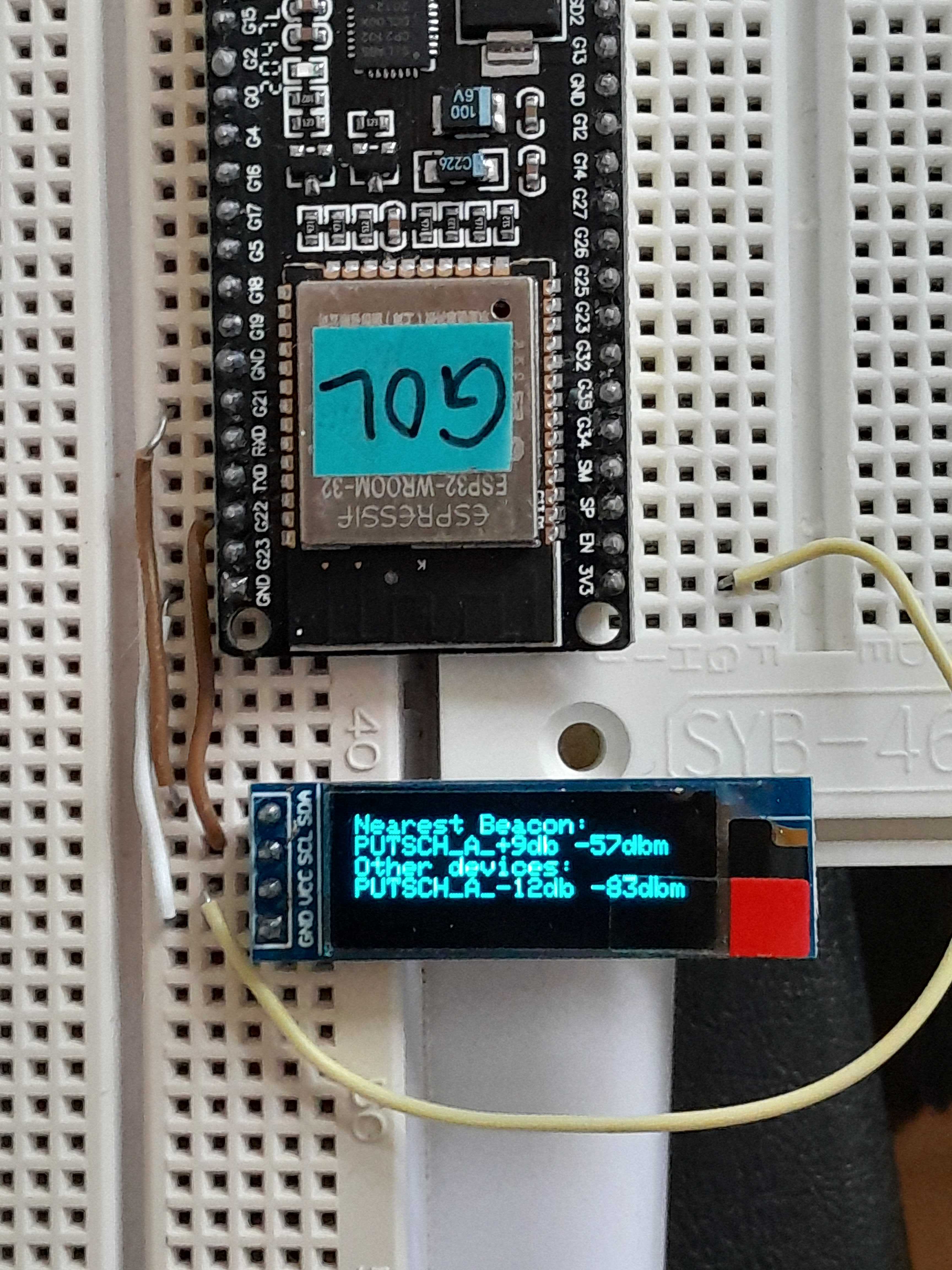
As a display, a so called 0.91 OLED[1] Display is used. Manufacturer unknown. It is connected via SPI. On lcdwiki.com[2] product informations including the schematics can be found. It is stated that the IC diver is a SSD1306. The SSD1306 can be interfaced with SPI or I2C. The datasheet states[3, page 20], states the slave address in I2C mode:
"Either “0111100” or “0111101”, can be selected as the slave address of SSD1306."
-[3, page 20]
0111100 is 0x3C, 0111100 is 0x3D.
References
[1] AZ-delivery product link: https://www.az-delivery.de/products/0-91-zoll-i2c-oled-display
[2] http://www.lcdwiki.com/0.91inch_IIC_OLED_Module_SSD1306_SKU:MC091GX
[3] http://www.lcdwiki.com/res/MC091GX/SSD1306-Revision%201.5.pdf
Electromechanical interface[Bearbeiten]
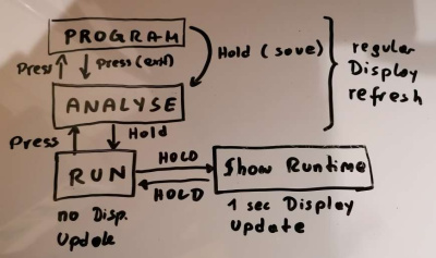
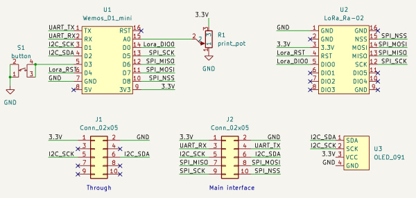
The LoRa boards have a button and a potentiometer. The button is used to change the device mode. The potentiometer is used to change a value in the range of 1-10.
Schematics[Bearbeiten]
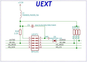
COMMENT - Only connect GND, VCC, TX and RX for UART connection to Olimex! Olimex is also I2C Master.
Software[Bearbeiten]
Control commands[Bearbeiten]
| QUEST | PLAYLIST | source: meaning |
|---|---|---|
| 254 | 254 | LOCATION |
| 253 | 0-100 | VOLUME |
| 0-250 | 0-250 | PLAY QUEST PLAYLIST |
Error Codes[Bearbeiten]
| code | source: meaning |
|---|---|
| 0 | olimex: default state (olimex ready) |
| 1 | olimex: is playing |
| 2 | olimex: SD card error (f.e. folder not found) |
| 10 | endnode: no olimex answer |
| 11 | endnode: doubletrigger avoided |
Libraries[Bearbeiten]
OLED display[Bearbeiten]
For the communication with the OLED display, <Adafruit_GFX.h> and <Adafruit_SSD1306.h> are used. As the display can be interfaced with SPI or I2C, <SPI.h> for SPI and <Wire.h> for I2C are also used. The OLED display is interfaced based in the aranacorp.com[1] example.
This example uses I2C as interface and addresses the display with 0x3C. This means a second display could be connected, that uses address 0x3D:
display.begin(SSD1306_SWITCHCAPVCC, 0x3C); // Address 0x3C for 128x32
Adafruit_SSD1306 display = Adafruit_SSD1306(128, 32, &Wire);
References
[1] https://www.aranacorp.com/en/using-a-0-91in-oled-display-with-arduino/
LoRa module[Bearbeiten]
Rollen im Netzwerk[Bearbeiten]
Gateway[Bearbeiten]
Der Gateway ist an einen Computer angeschlossen und somit Schnittstelle zur Spielelogik.
The gateway knows several modes.
Game mode
Game mode is ment to be the reguar interface to the game-logic. The gateway sends any command received via serial.
manual mode
In manual mode a command can be entered via serial promts.
Illuminate mode
In Illuminate-mode, the network illuminates its boarders. It is used fo measuring the reach of the network. Therefore the gateway sends a broadcast. Every repeater that receives the broadcast waits a random amount of time before it resends the message. The RSSI can be measured to determine the signal strength to any repeater.
Stationary[Bearbeiten]
Sind Netzwerkteilnehmer die sich nicht bewegen können. (z.B. Drucker)
Mobile[Bearbeiten]
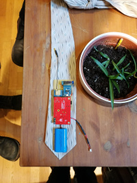
Sind Netzwerkteilnehmer die sich bewegen können oder auch Radios, die sich zwar nicht bewegen aber ansonsten baugleich sind, mit einem Audioboard dabei. (Radios + Spielerinnen)
- Custom PCB
- Lora Modul mit Antenne
- Wemos D2 Mini Prozessor
- Mini Display
- Powerbank/Lipo Akku
- Olimex Audio Board Esp32 ADF
- SD Karte mit Audiofiles
- Bone Conductor Transducer
Repeater[Bearbeiten]
Dienen ausschließlich zum Wiederholen des Funksignals und adressieren der Teilnehmer – somit ist der Netzwerkaufbau etwas unabhängiger vom Spiel-Aufbau. Erfüllen also die Funktion eines Repeaters. A repeater must know two things:
1) Should it repeat the packet in order that it is passed to the receiver?
1) Should it repeat the packet in order that it is passed to the gateway?
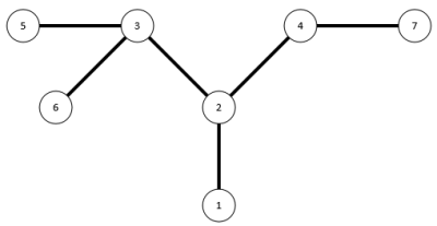
This is realised by storing three arrays, where the array-size equals the maximum subnets. The first index in one array stores the repeaters next neighbours address. By reading it out, the repeater can determine if it is the next possible sender. By scanning the other two arrays, it can determine if it should repeat the packet. One array is for sending from the gateway, the other is for sending back to the gateway.
As an example we can look ate node 3 with 9 maximum nodes.
| 5 | 6 | 0 | 0 | 0 | 0 | 0 | 0 | 0 | 0 |
| 2 | 1 | 0 | 0 | 0 | 0 | 0 | 0 | 0 | 0 |
| 5 | 6 | 0 | 0 | 0 | 0 | 0 | 0 | 0 | 0 |
Messgerät[Bearbeiten]
Das Messgerät zeigt nur die Signalstärke und das subnet an.
Combining LoRa with WLAN[Bearbeiten]
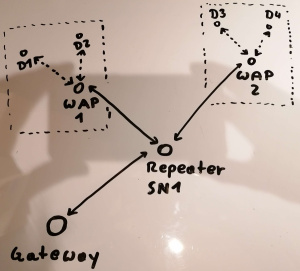
To increase speed, LoRa is going to be combined with WLAN. As measurements showed, bigger packet-sizes do not have as much negative impact on the network speed as much sending. Therefore WLAN Acces Points are implemented.
A WLAN Acces Point is treaded like a stationary device. It buffers all necessary data of all devices, connected via WLAN to it. With a special command, a bigger packet can be read out, containing all WLAN-devices data.
Lora Packet-Structure[Bearbeiten]
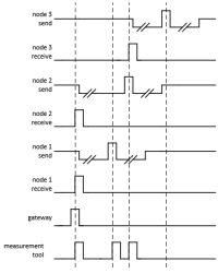
Our initial idea was to send many small packets, to increase data throughput. However measurements showed that the send-process comsumes more time than increasing the packet size. So less but bigger packets seem to be faster than more but smaller packets.
| Byte: | 1 | 2 | 3 | 4 | 5 | 6 |
|---|---|---|---|---|---|---|
| Purpose: | receiver-address | command | data | sender-address (1) | packet-id | subnet |
| Byte: | 1 | 2 | 3 | 4 | 5 | 6 |
|---|---|---|---|---|---|---|
| Purpose: | receiver-address (1) | command | data | sender-address | packet-id | position |
On WLAN Access Points, a bigger packet can be read out.
| Byte: | 1 | 2 | 3 | 4 | 5 | 6 | ... | n-2 | n-1 | n |
|---|---|---|---|---|---|---|---|---|---|---|
| Purpose: | receiver-address (1) | amount of data (k) | packet-id | data 1 | sender-address 1 | position 1 | ... | data k | sender-address k | position k |
COMMENT - Packets need to be rearranged!
Network address table[Bearbeiten]
The role of a LoRa network device is set by its network address. This saves a seperate handling of the role beside its addressing. If the device is the gateway or a repeater, its address equals also the subnet the device is standing for.
| address | purpose |
|---|---|
| 0 | invalid |
| 1 | gateway |
| 2-9 | repeater |
| 10-49 | mobile endnodes |
| 50-149 | stationary endnodes |
| 254 | broadcast |
| 255 | invalid |
Address 0 and 255 are invalid, as there might be a hardware shortcut to GND or VCC in this case. Address 254 is for broadcasting. This means if the gateway addresses 254, every network device is receiving.
Command table[Bearbeiten]
This table shows the commands that can be sent via LoRa. The designation is ment to be a unique 4-Char name for defines.
COMMENT - The command numbers need to be rearranged/sorted once it's finished!
| command | name | data packet | designation |
|---|---|---|---|
| 10 | program | - | - |
| 0 | invalid | - | - |
| 246 | WLAN member data answer | special data format | WMDA |
| 247 | WLAN member data request | - | WMDR |
| 249 | illuminate | - | ILLU |
| 250 - 254 | unused | - | - |
| 253 | ping answer | RSSI of received ping | PNGA |
| 254 | ping request | - | PNGR |
| 255 | invalid | - | - |
I2C address table[Bearbeiten]
| address | device | comment |
|---|---|---|
| 0x3C | 0.91 OLED Display | default |
| 0x3D | 0.91 OLED Display | |
| 0x70 | Clock display | default |
Token Pass System[Bearbeiten]
Innere Stimme[Bearbeiten]
Knochenschallkopfhörer Interface[Bearbeiten]
Das Publikum wird begleitet durch eine sogenannte innere Stimme, die im eigenen Kopf drin zu einem spricht. Um diesen Effekt zu unterstützen werden Knochenschallkopfhörer benutzt, die den Schall über den Schädelknochen übertragen und somit die Ohren für Umgebungsgeräusche frei bleiben, während Audiofiles abgespielt werden.
Wir verwenden Conductor Transducer von adafruit.
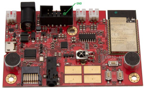
Olimex Audioboard[Bearbeiten]
Audio Modul für Radios und Publikum
Reference
Olimex product webpage with links https://www.olimex.com/Products/IoT/ESP32/ESP32-ADF/open-source-hardware
SD Karten Bespielprogramm
Python Programm, dass alle mp3 Files Namen in Ziffern übersetzt, damit sie in dieser Form auf die SD Karten gespielt werden können damit lokal am Board Befehle mit möglichst kleinem Datenvolumen interpretiert werden können, die per Lora verschickbar sind.
SD Karten Abspielprogramm
Enthält Funktionen das Abspielen der Audiofiles dynamisch gestalten, die flüssiges Wechseln zwischen Quests oder spontane Begegnungen inmitten von laufenden Quests ermöglichen. Geht Hand in Hand mit einer übersichtlichen Ordnerstruktur und sehr kleinen Snippets der Audioaufnahmen, die Sprünge zwischen Ordnern/Quests erlauben, sowie "Zurückkehren" zu bereits angefangenen Quests.
Ortung der mobilen Clients im Spiel[Bearbeiten]
Bluetooth Beacons[Bearbeiten]
Spiellogik[Bearbeiten]
Architektur[Bearbeiten]
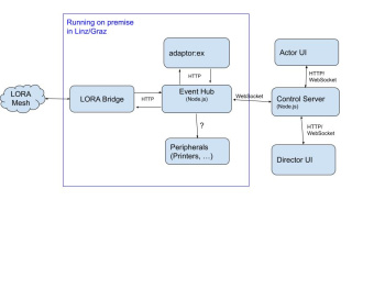
Event Hub[Bearbeiten]
The Event Hub is a piece of software
- receiving events from the LORA gateway and adaptor:ex
- receiving commands from the Director UI and the Actor UI via the Control Server
- changing the state in adaptor:ex
- sending commands to Players via the LORA gateway
- providing and pushing data to the Control Server (and thus, to the Director UI and the Actor UI)
- communicating with peripherals like printers
